Lessons Learned From Ben Eater's 8 Bit CPU to Designing Single Board Computer
This is what I’ve learned from my time attempting to design an 8 bit cpu to FPGAs, to designing a single board AVR based computer and OS. These topics were never really well investigated in school. I had taken computer science and mathematics courses, but never really breadboarded, soldered, or done any hardware/FPGA/architecture design in school.
Goals
In short I wanted a project that could challenge me, and bring some skills and insights into computing that was glossed over in university for me. I set out to build a breadboard CPU, then a single board computer, then a single board computer and FPGA GPU. Finally I decided that I would try and spend this time doing other things.
To preface, this project was probably too large and too vague for me to take on in the first place. It fizzled out due to a multitude of reasons. Mainly I no longer had interest in spending countless hours debugging electrical circuits, working with computers, designing a computer, all after a day of work on computers. I however feel that I learned a great deal. The detours I took along the way helped give me a more complete understanding of computation(from the practical side).
The topics I got to dabble in, were practically non-existent in my studies at university. From understanding Ohm’s Law, and actually applying it. To reading articles on timing attacks on the x86 microarchitecture. I still feel that although I no longer have the ambition to pursue computer related projects after work, I still do enjoy learning. And this project proved to me that computer work is probably best left as work.
Original Project
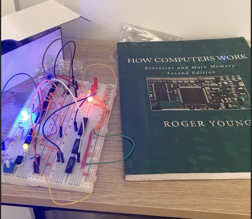
The original project was to follow along Ben Eater’s 8 Bit Breadboard CPU. I made good progress along that. Below is the 555 timer circuit and a single register.
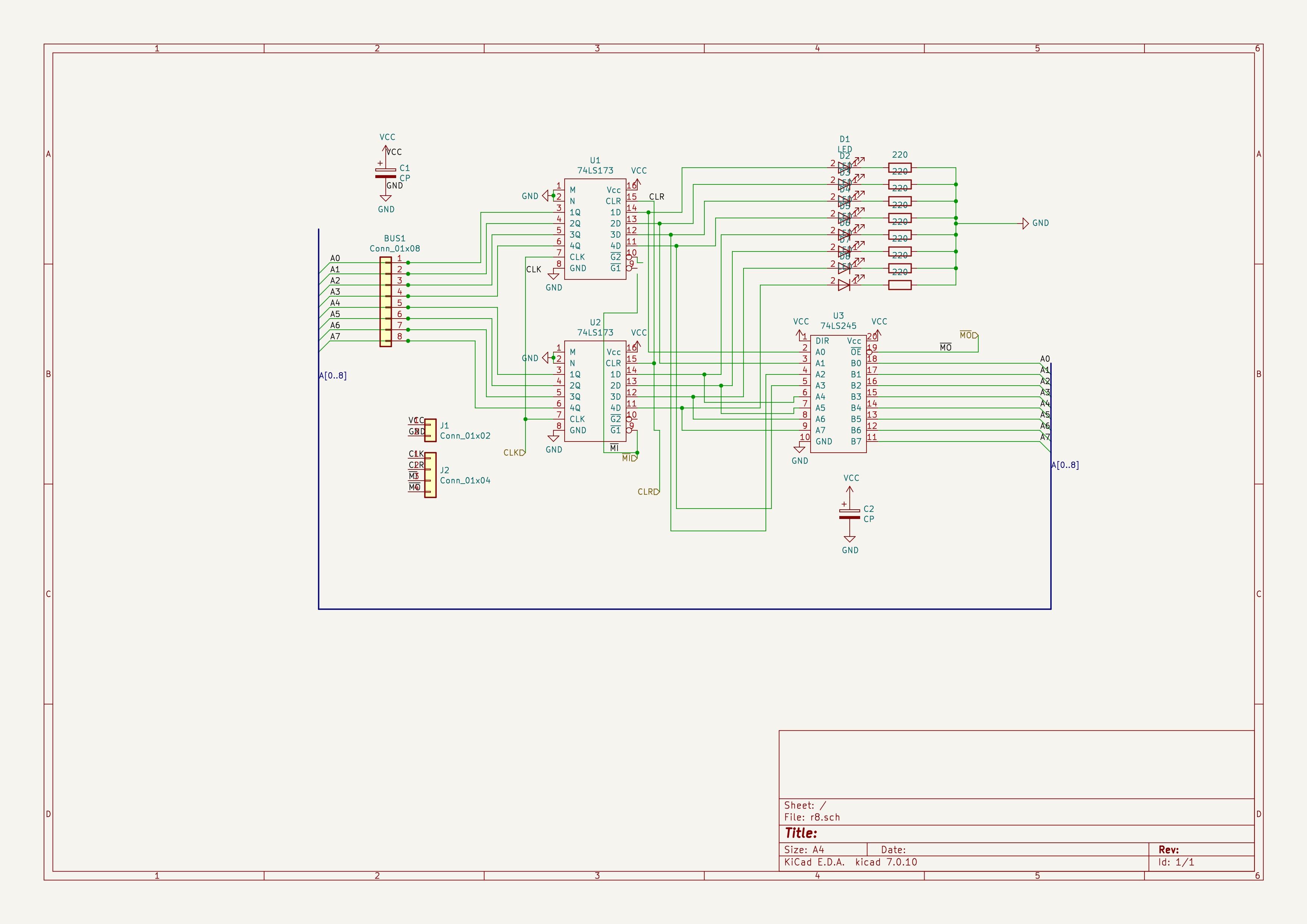
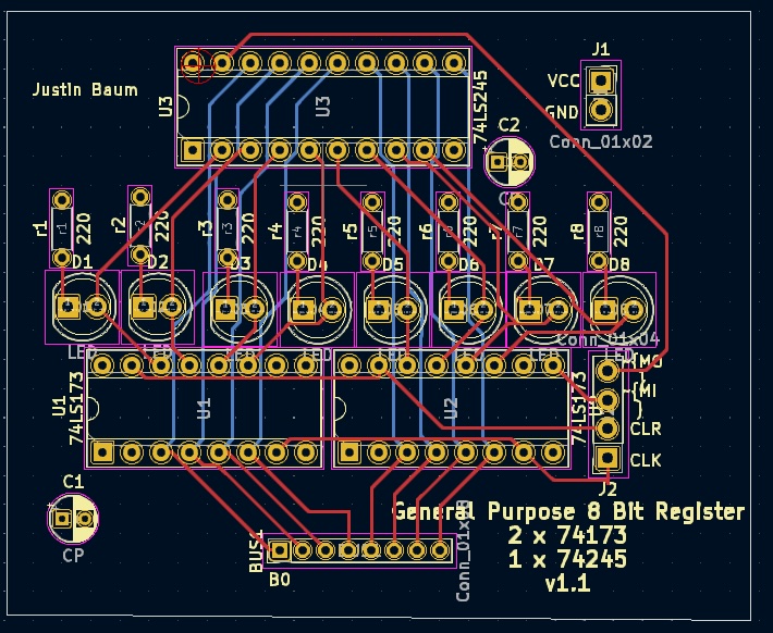
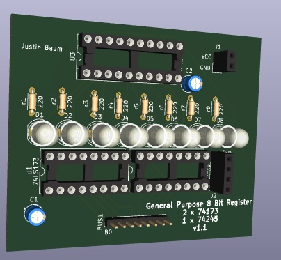
Later on my breadboarding got to be a little unreliable, so I began designing PCBs for a register and other circuits.
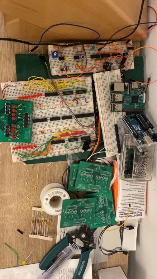
At this point the little table in my apartment had no more available space. This was the Fall and Winter of 2021. I decided I needed to come up with something new for the project. Living in a 300 ft\(^2\) apartment just did not give me liberty to take on a project of this magnitude.
I wish I had more details and things to show, but this was towards the end of 2021, it is currently 2024, and nothing too interesting or difficult came up.
Lessons
I learned quite a bit. Mainly how electricity works(lots of shorts and burning TTL chips because I still write it off as magic). What designing PCBs entails. Soldering was brushed up on a good bit. Overall I figured I was going to run out of space in my studio apartment, and there wasn’t much more to learn(although developing a microarchitecture would’ve been worthwhile in hindsight).
Redirection
At this point I wanted to continue down this path and needed a new project. I had inspiration from Matt Sarnoff’s Amethyst. This was an AVR single board computer, with the bulk of the work being the operating system. This felt more up my alley.
New Goals
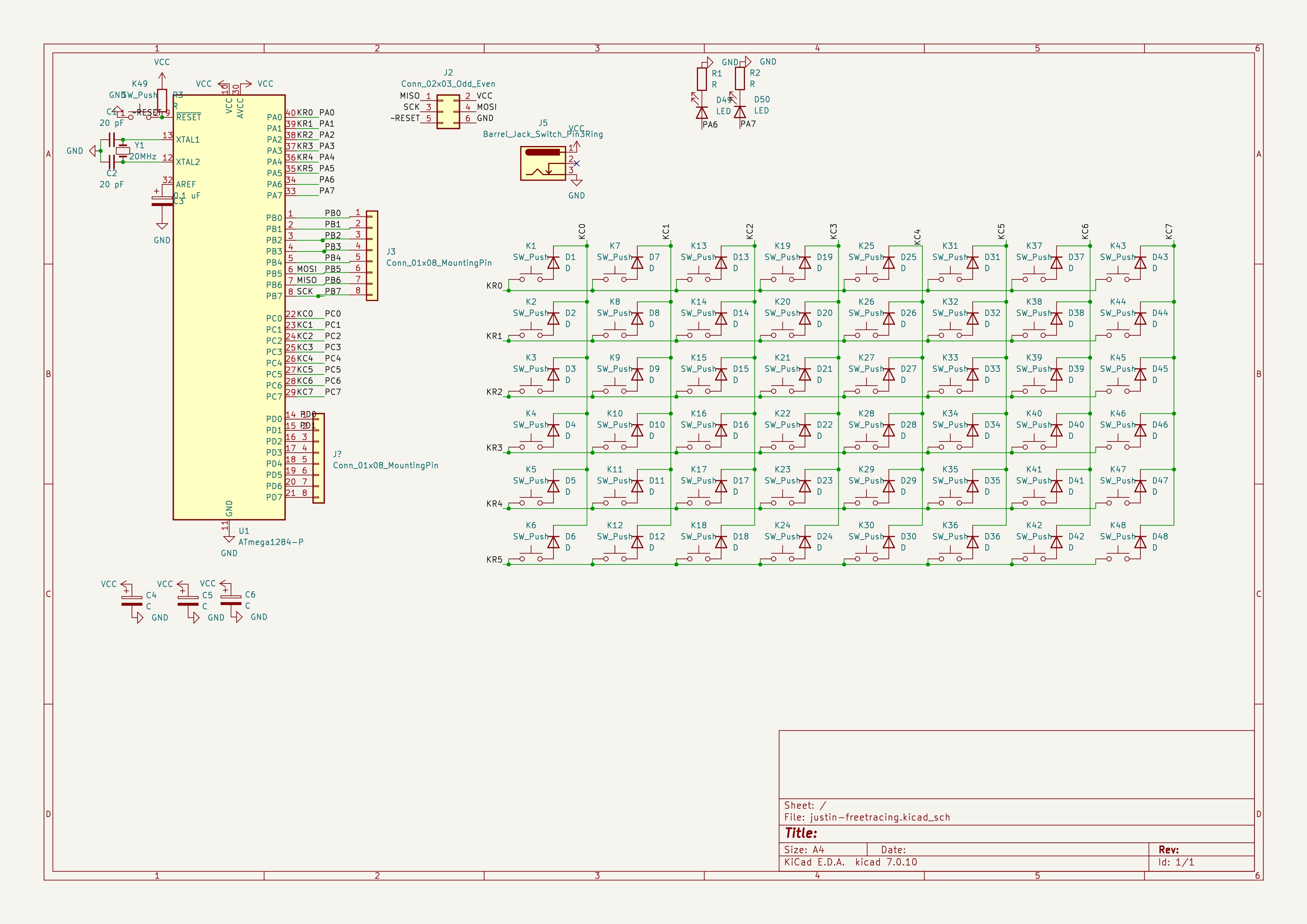
I learned very quickly that my practicality for Ben Eater’s 8 bit CPU was far fetched. My apartment was too small, this project takes commitment and space. I ran into the Matt Sarnoff’s Amethyst Project and decided with what I learned in Kicad, soldering, electricity, that I should be able to design a single board computer using a microcontroller(memory, IOs, etc handled on die).
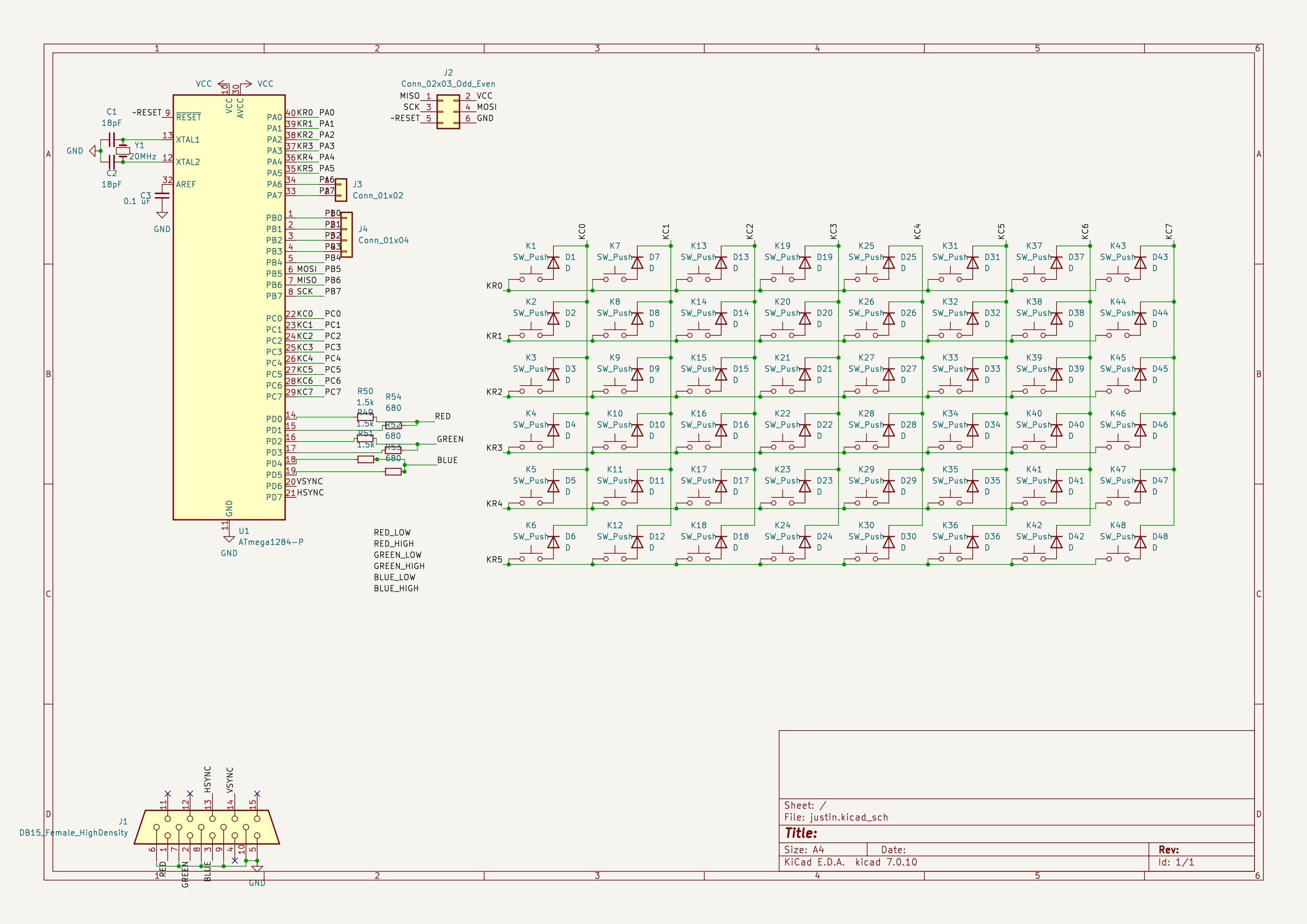
Picking a Microcontroller
I think here I just chose the same chip as Matt Sarnoff did. The chip chosen was the Atmega1284P. This chip came in the 44 PDIP package and had everything needed to build a minimalist OS(without of course user space/kernel space or really any hardware capabilities that would make having a program space possible). Instead the idea was to have everything statically compiled and linked, including the program space, have some routines for keyboard input and other abstractions, and call it a day. This means that memory management is non-existent, and that this would basically not be an Operating System in any sense of the term.
The Atmega1284P had a very nice spec sheet for us.
- 32 registers
- Capable of 20 MHz clock
- 128 kb program memory
- 16 kb RAM
- 10 bit ADC
- Originally this was for VGA output, but was dropped for 1 way 8 bit bus
- Pin interrupt & timer interrupts
- Originally wanted keyboard to be pin interrupt, but with writing VGA signals out(required rigorous timing), went with a polling design
Original Design
Originally I wanted a VGA output, keyboard input, some programs and such. I had originally designed the video output to be with a VGA port.
However when I was writing out examples of the OS, the VGA timing and my bad assembly skills was leaving me with near less than 3% clock cycles for other tasks. The best explanation I can give for the following code is, we’re giving an analog signal that is timed. We scan line by line of the screen, with extra run off before and after to sync timing. This has to do with how most monitor/TV outputs were CRT, and the beam would scan across the screen left to right, up to down. Calculating our resolution, 400x300, then finding how long each signal needs to be on/off for is calculated in the comments. After extrapolating, and calculating how much CPU time there would be before this routine got called again by the timer interrupt, it was just infeasible to do anything truly meaningful.
This was originally written for a test breadboard for an Atmega328P(was using this board to test)
#define __SFR_OFFSET  0x00
#ifndef __AVR_ATmega328P__
#define __AVR_ATmega328P__
#endif
#include <avr/io.h>
#include <avr/interrupt.h>
.global G_LINES

#define PE_LOW  0b0001;
#define PE_HIGH  0b010;
#define HSYNC  0b0100;
#define VSYNC  0b1000;

; http://tinyvga.com/vga-timing/800x600@60Hz
; 400 x 300
; 50 x 37

; Visible Area:
	; 400 px <- 20 uS = 400 clocks @ 20 MHz
	; 8 clock cycles per 8 bits
; Front Porch <- 1 uS = 20 clocks
	; 20 px
; Sync Pulse <- 3.2 uS = 64 clocks
	; 64 px
; Back Porch <- 2.2 uS = 44 clocks
	; 44 px

; Vertical Timing
	; 600 px <- Visible
	; 1 <- Front Porch
	; 4 <- Vertical Sync
	; 23 <- Back Porch

.macro ONECHAR
; 8 Clock Cycles; Z: address of char data, X: current VRAM position
ld ZL, X+				; 2cc ZL = (X++)
lpm r21, Z			; 3cc *Z
out PORTD, r21	; 1cc Out 8 bits of prog mem line
out PORTB, r19	; 1cc /PE LOW <- Load Pixel Data to Shift
out PORTB, r18 	; 1cc /PE HIGH <- Clock pumps
.endm

.global TIMER0_COMPA_vect
TIMER0_COMPA:
TIMER0_COMPA_vect: ; 7 - 10 cycles to get
	cli
	push r18
	push r19
	push r24
	push r25
	lds r24, G_LINES
	lds r25, G_LINES+1
	adiw r24, 0x01 ; G_LINES++
	; if G_LINES < 602
	cpi r24, 0x5A ; Compare lower
	ldi r18, 0x02 ; 2
	cpc r25, r18  ; compare higher
	brcc G_LINES_OVER_602
	ldi r18, PE_HIGH;
	ldi r19, PE_LOW;
	ONECHAR
	ONECHAR
	ONECHAR
	ONECHAR
	ONECHAR
	rjmp TIMER0_EXIT

G_LINES_OVER_602:
	; If lines == 628
	cpi r24, 0x74; Compare lower
	cpc r25, r18 ; Compare higher
	brne G_LINES_NOT_628
	ldi r24, 0 ; G_LINES = 0
	ldi r25, 0 ; G_LINES = 0
	rjmp TIMER0_EXIT


G_LINES_NOT_628:
	; If lines < 605
	cpi r24, 0x5D ; compare lower
	cpc r25, r18 ; compare higher
	brcc G_LINES_OVER_605
	rjmp TIMER0_EXIT

G_LINES_UNDER_605:
	; ...
	rjmp TIMER0_EXIT

TIMER0_EXIT:
	sts G_LINES+1, r25
	sts G_LINES, r24
	pop r25
	pop r24
	pop r19
	pop r18
	sei
	reti
Finally I decided, enough was enough, I should probably buy an FPGA and design an auxilary circuit to handle communications over a bus and a VGA. This would later be decided to just be an open bus, and I’d read the output with an arduino/Rasp Pi/etc until I decided to come back to designing an FPGA.
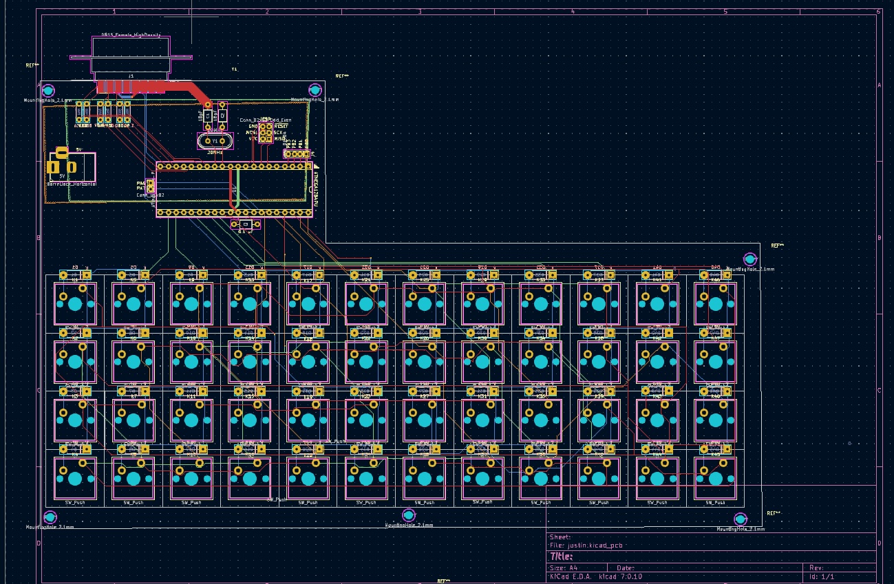
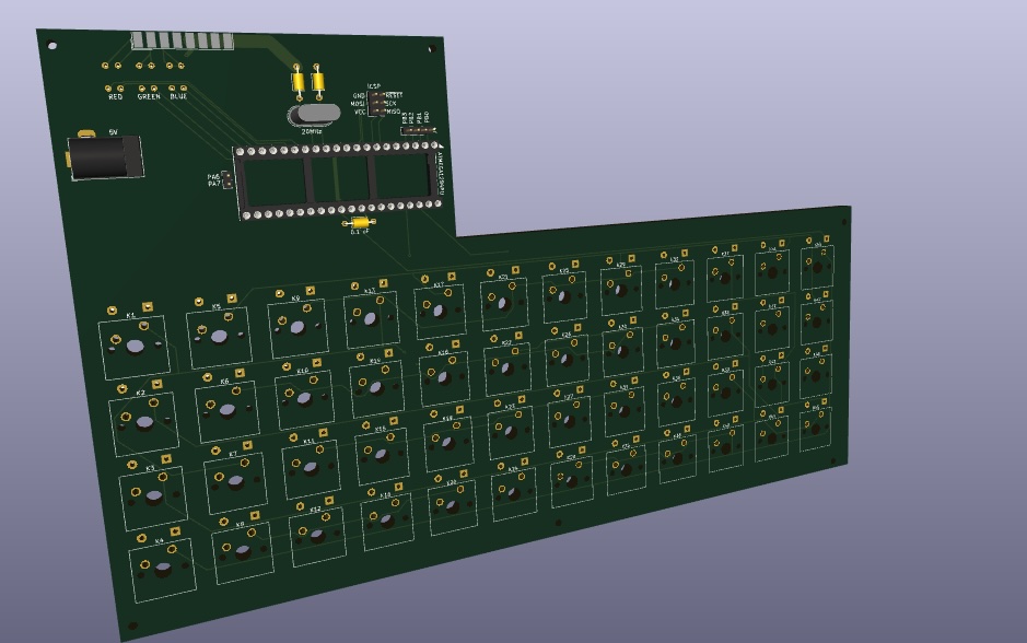
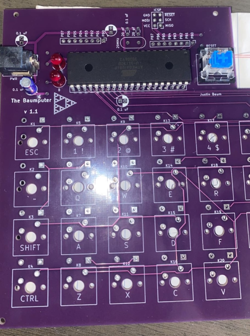
Open Bus Design
Tiny note, Baumputer was a running joke from high school because I spent too much time on Wikipedia and knew too many pieces of trivial facts. One time my chemistry professor asked the class what chemical makes shaving cream foam, and I immediately knew it was sodium lauryl sulfate because I’ve had this exact question googled at some point in my life. I decided it was a fun name.
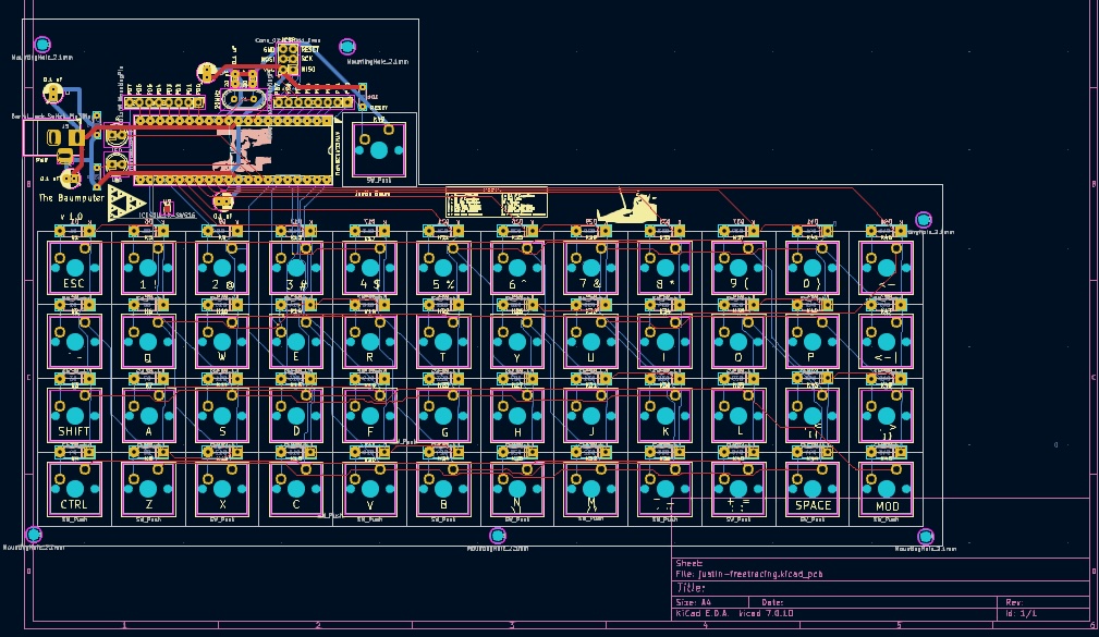
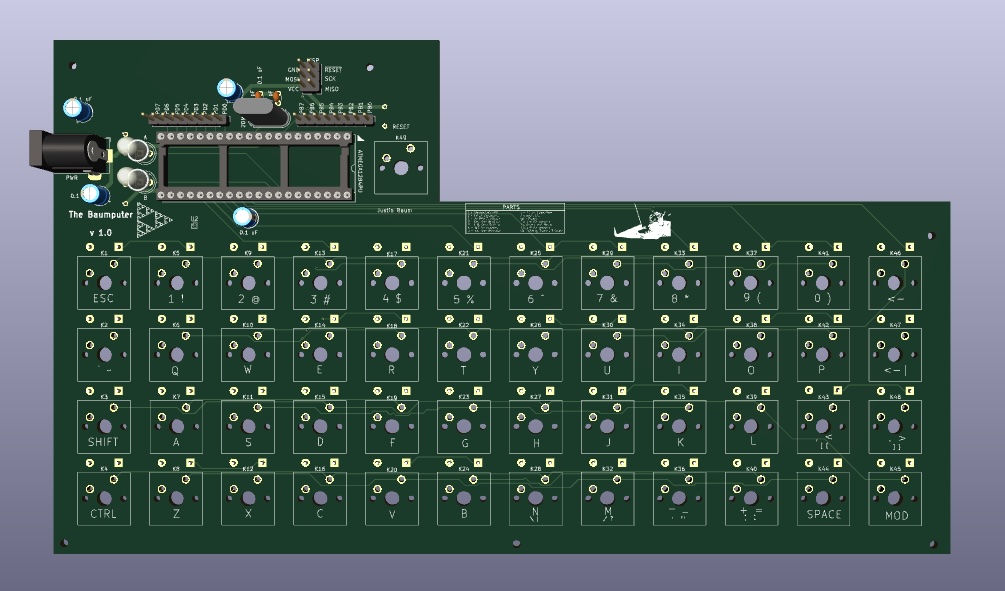
The Sierpinski Triangle printed on the PCB was just me learning and practicing how to print graphics.
OS Design
The idea behind much of this was to have an interrupt run on a cadence that would handle a few things on a regular cadence(this would be the heart of the single address space program that would seemingly act like my OS).
- Writing to a shared bus on a regular cadence(this would be read as our video output at some point)
- Polling the keyboard, it would output a signal on 6 pins separately, and read in on 8 pins
- This would allow us to read a single key of a 48 key keyboard
- Iterate lights, this allows us to have an extra set of outputs, debugging etc
Keyboard Polling
Overall the idea was to have keyboard inputs be asynchronous. The keyboard
buffer would be filled and used between the routine adding characters to the
buffer, and programs reading this buffer. There is one blocking call that I
found utility enough in to add, and that’s keyboard_wait_for_line(char
*buffer, uint8_t size).
keyboard_driver.h
#include <avr/io.h>
#include <stdbool.h>
#ifndef keyboard_driver_h
#define keyboard_driver_h

#define KEYBOARD_BUFFER_LENGTH 64
#define GET_KFLAG(FLAG) GET_FLAG(FLAG, keyboard_status)
#define NGET_KFLAG(FLAG) NGET_FLAG(FLAG, keyboard_status)
#define SET_KFLAG(FLAG) SET_FLAG(FLAG, keyboard_status)
#define UNSET_KFLAG(FLAG) UNSET_FLAG(FLAG, keyboard_status)
static char keyboard_buffer[KEYBOARD_BUFFER_LENGTH];
static uint8_t keyboard_buffer_index;
static uint8_t keyboard_status;

const uint8_t K_FLAG_BUFFER_EMPTY;
const uint8_t K_FLAG_BUFFER_FULL;
const uint8_t K_FLAG_READ_LAST;
const uint8_t K_FLAG_RESERVED3;
const uint8_t K_FLAG_RESERVED4;
const uint8_t K_FLAG_RESERVED5;
const uint8_t K_FLAG_RESERVED6;
const uint8_t K_FLAG_RESERVED7;

void read_keyboard(void);
char kgetc(void);
uint8_t kputc(char c);
void keyboard_wait_for_line(char *buffer, uint8_t size);
void keyboard_setup(void);
#endif
There are some macros above, these are macros I used for originally being able to inline register actions, but this ended up being a bit unwieldy, and decided against it. Instead it was just a nice macro for handling that static flag.
#define GET_FLAG(FLAG, REGISTER) REGISTER & FLAG
#define NGET_FLAG(FLAG, REGISTER) ~REGISTER & FLAG
#define SET_FLAG(FLAG, REGISTER) REGISTER |= FLAG
#define UNSET_FLAG(FLAG, REGISTER) REGISTER &= ~FLAG
Below is a description for
keyboard_driver.c.
Instead of putting more code, here’s what should’ve been documentation as a
table here.
| Function | Description |
|---|---|
| read_keyboard() | A system call to be called by the interrupt handler. This is the routine to be called by the system. It handles scanning out, and reading in, adding the character to the buffer and such. |
| kgetc() | This is meant to retrieve the last character input |
| kputc(char) | This is for manipulating the buffer if needed |
| keyboard_wait_for_line(char*, uint8_t) | This is a blocking call. This will wait for a character array followed by a new line to be input. It will copy the buffer to the pointer location and exit when finished |
| keyboard_setup() | This is call made by original entry point to handle setting global registers to designate what IO ports are read/write for the keyboard driver |
Handling Timing
So the main program has a call to set up our timer interrupt. This allows us to run the keyboard reader on a regular cadence, output the bus, handle random number generation and light manipulation.
void setup(void) {
  // Configure ISR Interrupt
  screen_setup();
  keyboard_setup();
  master_lights_setup();
  configure_interrupt();
}
If we take a look at the configure_interrupt() routine, we’ll find.
void configure_interrupt(void) {
  // 1024 Prescaler
  TCCR0B = (1 << CS02) | (1 << CS00);
  // 76 Hz
  TIFR0 = 1 << TOV0;
  // Enable Interrupt
  TIMSK0 = 1 << TOIE0;
}
This means our Timer0 interrupt will run on a 76 Hz cadence. This is that interrupts routine.
ISR(TIMER0_OVF_vect, ISR_BLOCK) {
  read_keyboard();
  output_video_ram();
  increment_master_lights();
}
If we take a look at the interrupt table we will find the routine at address 0x0000003c:
00000000 <__vectors>:
   0:	0c 94 e9 00 	jmp	0x1d2	; 0x1d2 <__ctors_end>
   4:	0c 94 08 01 	jmp	0x210	; 0x210 <__bad_interrupt>
   8:	0c 94 08 01 	jmp	0x210	; 0x210 <__bad_interrupt>
   c:	0c 94 08 01 	jmp	0x210	; 0x210 <__bad_interrupt>
  10:	0c 94 08 01 	jmp	0x210	; 0x210 <__bad_interrupt>
  14:	0c 94 08 01 	jmp	0x210	; 0x210 <__bad_interrupt>
  18:	0c 94 08 01 	jmp	0x210	; 0x210 <__bad_interrupt>
  1c:	0c 94 08 01 	jmp	0x210	; 0x210 <__bad_interrupt>
  20:	0c 94 08 01 	jmp	0x210	; 0x210 <__bad_interrupt>
  24:	0c 94 08 01 	jmp	0x210	; 0x210 <__bad_interrupt>
  28:	0c 94 08 01 	jmp	0x210	; 0x210 <__bad_interrupt>
  2c:	0c 94 08 01 	jmp	0x210	; 0x210 <__bad_interrupt>
  30:	0c 94 08 01 	jmp	0x210	; 0x210 <__bad_interrupt>
  34:	0c 94 08 01 	jmp	0x210	; 0x210 <__bad_interrupt>
  38:	0c 94 08 01 	jmp	0x210	; 0x210 <__bad_interrupt>
  3c:	0c 94 0a 01 	jmp	0x214	; 0x214 <__vector_15>
  40:	0c 94 08 01 	jmp	0x210	; 0x210 <__bad_interrupt>
  44:	0c 94 08 01 	jmp	0x210	; 0x210 <__bad_interrupt>
  48:	0c 94 08 01 	jmp	0x210	; 0x210 <__bad_interrupt>
  4c:	0c 94 08 01 	jmp	0x210	; 0x210 <__bad_interrupt>
  50:	0c 94 08 01 	jmp	0x210	; 0x210 <__bad_interrupt>
  54:	0c 94 08 01 	jmp	0x210	; 0x210 <__bad_interrupt>
  58:	0c 94 08 01 	jmp	0x210	; 0x210 <__bad_interrupt>
  5c:	0c 94 08 01 	jmp	0x210	; 0x210 <__bad_interrupt>
  60:	0c 94 08 01 	jmp	0x210	; 0x210 <__bad_interrupt>
  64:	0c 94 08 01 	jmp	0x210	; 0x210 <__bad_interrupt>
  68:	0c 94 08 01 	jmp	0x210	; 0x210 <__bad_interrupt>
  6c:	0c 94 08 01 	jmp	0x210	; 0x210 <__bad_interrupt>
  70:	0c 94 08 01 	jmp	0x210	; 0x210 <__bad_interrupt>
  74:	0c 94 08 01 	jmp	0x210	; 0x210 <__bad_interrupt>
  78:	0c 94 08 01 	jmp	0x210	; 0x210 <__bad_interrupt>
  7c:	0c 94 08 01 	jmp	0x210	; 0x210 <__bad_interrupt>
  80:	0c 94 08 01 	jmp	0x210	; 0x210 <__bad_interrupt>
  84:	0c 94 08 01 	jmp	0x210	; 0x210 <__bad_interrupt>
  88:	0c 94 08 01 	jmp	0x210	; 0x210 <__bad_interrupt>
Note there were examples of me trying to use assembly to cut clock cycles for the VGA timing, see here.
Overall
This project was too open ended, too ambitious and impractical for me at the time. Now it is slightly a bit of burnout of working with computers at this point. I decided to take on new hobbies, travel, and reduce time spent in front of the computer. The pandemic and and my sky rocketing computer time, prefaced with 2018/2019 projects, work, and school had probably given me unhealthy habits.
I recall in 2017 my first completed true project, and how healthy that work was. I was in high school, I had requested to work on a chess engine as a final senior project. I worked on it for the course of 3 months. This was surrounded with 6 of my other 7 classes, varsity basketball, and working over the weekends. This meant I was probably working on this project 5-10 hours a week. At this time, it was practically all of my computer time a week. My school did not offer computer science courses, or AP Computer Science, so this was very much open ended, however I did have to file project goals, expectations, weekly check ups, and this really helped me in having a final result.
End Notes
I have a feeling this will be a close for projects for some time. I may find myself coming back, but at this point I have been working on having less time with computers and healthier hobbies. In between my last post and this one I have begun to travel a good bit. I have ridden 14k miles on two different motorcycles. Ridden in Italy(Tuscany), and round trips to Skyline Drive(VA), and Berkshires(MA). I have plans on doing a motorcycle ride to Canada, and a ride of Skyline Drive plus the Blue Ridge Parkway in the future.